REFERENCE DATA
TEST ID
Each test in the database is assigned a unique name, usually based on the specimen designation in the cited reference.
REF/SOURCE
Reference abbreviations are described at the top of the Reference List, in the final section of this report. The database sometimes gives multiple references, especially where the primary source is unpublished or was superseded by a more complete report.
TABLE 1: DATABASE FIELDS
|
Reference
Data |
Loading Data |
||
|
Test ID |
|
Slab |
Slab description (if any) |
|
Ref/Source |
Reference document(s) |
Col Axial |
Applied column axial load |
|
Test Date |
|
Config |
Configuration (1- or
2-sided) |
|
Lab |
|
Control |
Beam or Column tip control |
|
Investigator |
|
Loading |
Loading protocol |
|
Engineer |
designer, for qualification
tests |
Dy |
Reference deflection |
|
Sponsor |
|
Notes |
Summarizes atypical
conditions |
|
Last Update |
date of data entry |
Results |
|
Connection Data |
Y(xDy) |
Observed yielding |
|
|
Intent |
intended use of the tested
detail |
B(xDy) |
Observed buckling,
distortion |
|
Condition |
|
F(xDy) |
Observed fracture |
|
F350 Type |
FEMA 350 connection type |
FracRate |
Fracture rate |
|
Type |
Connection type |
Stop Condition |
|
|
Piece Details |
|
UndefPRmx |
Undefined plastic rotation |
|
Weld Loc’n |
Indicates which pieces are
welded |
PHPRmax |
Plastic rotation at hinge |
|
TweldDet |
Weld detail at top flange |
PZPRmax |
Plastic rotation in panel
zone |
|
BweldDet |
Weld detail at bottom
flange |
CLPRmax |
Plastic rot’n at col.
centerline |
|
Wtype |
Weld type |
ED[k-’] |
Energy dissipation [ft-k] |
Specimen Data |
Dmax |
Maximum deflection, Dmax |
|
|
ColStl |
Column steel
grade |
P (or M) at
Dmax |
|
|
CFm |
Col. flange Fy
from mill test |
Deflection at
P/Mmax |
|
|
CWm |
Col. web Fy from mill test |
P/Mmax |
Maximum force or moment |
|
CFc |
Col. flange Fy from coupon |
1%D |
1% deflection (calculated
field) |
|
CWc |
Col. web Fy from coupon |
P1%D |
P (or M) at 1%D |
|
Column |
Column size |
P2%D |
P (or M) at 2% deflection |
|
ColWt |
Column weight |
P3%D |
P (or M) at 3% deflection |
|
ColHt |
Column height [ft] |
P4%D |
P (or M) at 4% deflection |
|
BmStl |
Beam steel grade |
Dtmx/Lcl |
Total story drift
(calculated field) |
|
BFm |
Bm. flange Fy from mill test |
Add’l Result |
For results in other
formats. |
|
BWm |
Bm. web Fy from mill test |
|
|
|
BFc |
Bm. flange Fy from coupon |
|
|
|
BWc |
Bm. web Fy from coupon |
|
|
|
Beam |
Beam size |
|
|
|
BmWt |
Beam weight |
|
|
|
Lcl |
Bm tip-to-col centerline length [in] |
|
|
|
Lh |
Hinge-to-col centerline
length |
|
|
|
CntPl |
Continuity plates |
|
|
|
DbPl |
Doubler plates |
|
|
|
Web Conn |
Web connection type |
|
|
CONNECTION DATA
INTENT
In general, this refers to the intended use of the connection being tested, not the intent of the test itself. In some cases, however, “parameter study” is used to indicate preliminary details not intended for use on actual projects. Because every test is in some ways a parameter study, this designation is reserved for proprietary details for which the other typical designations could be misleading.
Intent options represented in the database include:
new Tests of specimens fabricated to represent new construction. Pre-Northridge connections are classified this way if they are tested in sound, as-built condition, even though they are no longer used for new buildings. Tests that could represent either new construction or modification are generally classified as “new” unless modification is specifically indicated by the cited reference.
repair Tests of specimens with damage (either real or simulated) repaired—that is, with the connection restored to its original type.
modification Tests of specimens designed and fabricated specifically to change the mode of behavior relative to the pre-Northridge connection. “Modification” is often coupled with “repair.”
damaged Tests of specimens with known damage, usually performed to assess remaining capacity.
CONDITION
Condition notes are used to record material or fabrication defects, material reuse, or other pre-test conditions specifically reported in the source document. The condition, if unusual, is frequently related to the INTENT of the test.
Where applicable and appropriate, the tested connection is classified with one of the connection designations given in FEMA 350. This information is for the convenience of users studying a certain FEMA 350 connection type; it does not indicate conformance of the test specimen with FEMA 350. That is, the database may list an F350 TYPE even if some of the tested conditions do not exactly match those required for prequalification by FEMA 350. For example, FEMA 350 prequalification may be limited to certain member sizes or may require a specific weld access hole shape or beam web connection. A database connection may not meet those requirements but may match the general design intent and philosophy of the FEMA 350 connection type. For such a test, this database field usually lists the FEMA designation that most closely matches the test’s method of transferring flexural forces.
Database abbreviations in this field are the same as those given
in FEMA 350:
Prequalified welded fully
restrained (FR) connections:
WUF-B Welded
unreinforced flange-bolted web
WUF-W Welded unreinforced flange-welded web
FF Free flange
WFP Welded flange plate
RBS Reduced beam section
BUEP Bolted unstiffened end plate
BSEP Bolted stiffened end plate
BFP Bolted flange plate
Prequalified
partially restrained (PR) connections:
DST Double split tee
Proprietary
connections
SP Side plate
SW Slotted web
BB Bolted bracket
The default connection type is pre-Northridge (PreNR). A PreNR connection is one designed to transfer moment from a prismatic beam to a column primarily by means of complete joint penetration groove welds of the beam flanges. The most common pre-Northridge connections were made with no notch-toughness requirements and had their backing bars left in place after welding. Thus, repairs consisting of backing bar removal, gouging, and rewelding are still considered PreNR for database purposes. This classification is consistent with FEMA 267 (p.6-1). Variations on the PreNR connection involve the same intended flow of forces but with atypical materials or details, and these are noted as PreNR sub-classes.
Connection types represented in the database are abbreviated as follows (refer to Figure 1):
PreNR Pre-Northridge, with typical weld profiles and no notch toughness requirements. Backing bars are generally in place, but need not be. Beam web connections may be of any type. Repaired and damaged specimens are distinguished.
PreNR-NT Similar to PreNR, but with notch-tough welds and backing bars typically removed or welded in place.
PreNR-EndPl Similar to PreNR, but the beam is joined to an end plate, which is in turn bolted to the column face. Because end plates are connected to the beam end in the shop, weld profiles and details may vary from typical PreNR conditions.
PreNR-overlay Similar to PreNR, but with weld profiles built
up by additional layers of weld metal.
CP Cover plate. Oriented like the beam flange. Both the CP and the beam flange are joined to the column (as opposed to Flange Plates).
EndPl End plate. A means for attaching the beam to the column, typically a variation of another connection type (e.g. PreNR-EndPl or TBRBS-EndPl).
FF Free Flange. See FEMA 350. May be similar to WGap.
FP Flange plate. Oriented like the beam flange. Only the FP, and not the beam flange, is joined to the column (as opposed to Cover Plates).
Haunch An added piece with part oriented like the beam web and part oriented like the beam flange.
Pipe A means for transferring flexural forces through bolts. See FEMA 267A (p. 6-25).
RBS Reduced beam section. Generally, the edges of the beam flange are removed over a discrete length. Flanges with drilled holes are also classed as RBS.
Rib A piece oriented like the beam web, attached to either side of the beam flange.
Tree A strengthened extension of the column allowing the beam to be connected at a distance from the column face.
SidePl A piece oriented like the beam web, attached to the side of the beam flange.
WingPl A piece oriented like the beam flange, attached so as to increase the flange width.
WSlot A horizontal slot or elongated weld access hole in the beam or column web, generally adjacent to the member flange.
WGap A full-height section of the beam web removed at the beam end so as to eliminate undesirable conditions at weld access holes. May be similar to Free Flange (FF).
The use of “T” or “B” as the first one or two letters of the connection type indicates any difference in the means of force transfer between the top and bottom beam flanges. Examples of connection types and combinations include:
TBCP Cover plates on both the beam top and bottom flanges.
BRBS Reduced beam section at the beam bottom flange only; the beam top flange is similar to the pre-Northridge condition.
BHaunch, TCP Haunch at the beam bottom flange; cover plate at the beam top flange.
TBRBS, TBRib Reduced beam section and rib plates at both the top and bottom flanges.
The connection type by itself does not imply a particular shear connection type, weld type, weld detail, etc. In general, standard connection types in the database are consistent with distinct approaches identified by FEMA 267 and 267A. Newer FEMA 350 designations are given in some cases as described above. Connection type entries also indicate if the detail is proprietary to the test sponsors.
PIECE DETAILS
This information expands on the Connection Type by describing the size, arrangement, or material of various plates, slots, or flange cuts. For PreNR connections, this item is generally “na.” As space is limited, database users should consult the listed references for complete details.
Most of the descriptions under Piece Details are self explanatory. Various types of Reduced Beam Section details are described in FEMA 267A (p. 7-26).
WELD LOC’N
Weld location data indicates the assumed path of flexural forces through welds from the beam to the column. In PreNR connections, for example, the weld location is between the beam flange and the column at both beam flanges, and is indicated as: “TB:bm-col.” In haunch connections, however, the weld may join the column to the haunch flange only, to the haunch flange and web, or to both the haunch and the beam flange. In fully bolted connections, weld location is “na.”
WELD DETAIL
Weld detail refers to the welding position, the welding sequence, and the treatment of backing bars for the welds that are traditionally designed to transfer flexural forces. Abbreviations used in the database include:
CP Complete joint penetration groove weld, single-bevel.
DCP CP weld made in the downhand position, typical of field (or shop) welds for new construction.
OHCP CP weld made in the overhead position. Overhead welding simulates repair conditions and is sometimes specified to avoid weld access holes or passes interrupted by the beam web.
F Fillet weld.
DoubBev Double-bevel complete penetration weld.
Abbreviations regarding the backing bar include:
YB Backing bar used and left in placed.
NB No backing bar used, for example in some shop welds to end plates for which no backing is needed.
BR Backing bar removed after completion of the weld.
BW Backing bar left in place but welded to the column in order to reduce potential notch effects.
A sample weld detail entry is “DCP,BR,F,” indicating a complete penetration weld followed by removal of the backing bar and addition of a reinforcing fillet weld.
WELD TYPE
Weld type refers to the electrode used for the welds that are traditionally designed to transfer flexural forces.
SPECIMEN DATA
COLUMN, BEAM
Most of the tested sections were standard wide flange shapes. The few special cases are noted in the database with the following abbreviations:
bu Section built-up from plates.
BX Box or tube section.
CFT Concrete-filled tube.
cruc Cruciform section, fabricated from T shapes attached to the web of a wide-flange.
sim An H section or a European shape similar in size to the listed wide flange.
wk Weak axis column orientation with the beam framing to the column web. Unless noted “wk,” all beams frame to the column flange.
BASE MATERIAL PROPERTIES
The mill value refers to a mill test report or mill certification for the heat of steel from which the member came. The coupon value refers to the result of a coupon test from the actual member. Additional details on coupon testing may be available in the cited reference. Material test values are typically given only for the beam and column, not for additional plates or connectors.
COLUMN HEIGHT
Column height is recorded as the distance between lateral column restraints, as shown in Figure 3. For tests with column tip control, the column height is used to calculate equivalent story drift.
BEAM LENGTH
The beam length is recorded as the distance from the actuator or beam restraint to the centerline of the column, as shown in Figure 3. For tests with beam tip control, this length is used to calculate equivalent story drift.
CONTINUITY PL & DOUBLER PL
Plate thicknesses are given in inches. If the source document indicates a plate but does not report its thickness, the value “y” or “yes” is given. Refer to cited references for specific test details.
WEB CONN
The web or “shear” connection refers to the joining of the beam web to the column. Four typical types are abbreviated as follows and illustrated in Figure 2.
B Bolted
W Welded. Beam web welded directly to the column. A shear lug with erection bolts is typically present and may serve as a backing for the beam web-to-column weld.
WB Bolted with supplemental shear tab welds designed to provide some of the connection’s flexural capacity. In some connections intended for repair or modification, an existing bolted shear tab is welded to the beam web along its entire perimeter. In these cases, the shear connection is classified as Wpl whether or not the bolts remain in place.
Wpl Welded to the shear plate. The beam web is welded to the shear tab which is welded in turn to the column.
LOADING DATA
COL AXIAL
With most test specimens, only local “seismic” loads representing the effects of lateral deformation on a single beam-column substructure were applied. Some tests attempted to account for gravity loads or other frame effects as well. These loads, typically applied as axial loads to the column, are recorded here. The following abbreviations are used (other descriptions are self-explanatory):
C Compressive axial load applied to column.
T Tensile axial load applied to column.
CONFIGURATION
The two most common test configurations, “1side” and “2side,” are shown in Figure 3. For other configurations, refer to the cited reference. Two-sided configurations are listed in the database as two separate tests.
CONTROL
The two methods of application, “beam tip control” and “column tip control,” are shown in Figure 3. With beam tip control, the column ends are restrained and loads are applied at the end of the beam. With column tip control, the beam end and the bottom of the column are restrained while load is applied to the top of the column. Although the two methods involve different ways of recording response, the database records principal results in terms of equivalent story drift, which can be measured from either type of test.
LOADING
The nature of the applied load is either (quasi-) static or dynamic. Static loading is generally either cyclic or monotonic. Dynamic loading can be either cyclic or representative of a specific earthquake time-history. Most of the tests in the database used static cyclic loading. The precise load history, or protocol, can vary in terms of the target force or displacement levels or the number of cycles applied at each level.
REFERENCE DEFLECTION, Dy
Cyclic loading typically involves displacements that are increased with each cycle. The amplitude of the applied displacements is usually set in advance as a multiple of a value called the reference deflection, Dy. The reference deflection is usually calculated, not measured, as the value at which significant yielding is expected to begin. It is sometimes arbitrarily assigned.
Since Dy is not consistently defined or calculated, the database uses the 1% deflection as its basic deformation measurement. However, because many earlier tests reported results in terms of Dy, it is recorded in the database. More recent tests typically use load protocols based on total story drift, not yield deflection. Some earlier tests also report a yield load, Py, that corresponds to the reference deflection. These values have little meaning and are no longer recorded in the database.
NOTES
This field identifies and abbreviates typical conditions and common exceptions. It can also be used for sorting or querying the database. Unless noted, the following conditions apply to all tests:
A572Gr50 or Dual Cert column, A36 beam
FCAW beam flange-to-column weld with notch-toughness requirement
No applied column loads
No slab
One-sided beam-column configuration
Static cyclic loading
The following notes indicate exceptions to the typical conditions above:
1 a A572Gr50 or Dual Cert beam or beam nominal yield strength not reported
b A36 column or column nominal yield strength not reported
c A913 column
2 a FCAW weld without notch-toughness requirement at one or both beam flanges
b SMAW weld
c Weld type not reported
3 a Column axial tension applied
b Column axial compression applied
c Out-of-plane moments/axial loads applied to column to simulate bi-directional loading
4 Composite beam behavior simulated with partial slab
5 Listed test is one side of a two-sided configuration
6 a Static monotonic loading
b Dynamic loading, cyclic or time-history
c Static cyclic, near-field protocol
RESULTS
OBSERVED YIELDING, BUCKLING, DISTORTION, AND FRACTURE
The database records observed inelasticity with the pattern abbreviations of FEMA 267 (Section 3.2). The letters “T” or “B” in front of the damage type indicate whether the condition was observed at the beam top flange or the beam bottom flange or both (“TB”). The location of the damage in the specimen may also be recorded. In addition, the database records the approximate point in the loading history where the condition was observed by following the damage type with a bracketed value. If the bracketed value is in inches, for example, it indicates the peak displacement of the cycle in which the specified damage was observed. If the bracketed value is a unit-less integer, it represents a multiple of the reference deflection Dy. Otherwise, bracketed values may represent displacement in inches or total drift in percentage. If source documents do not specify when the observation was made, other bracket values (such as “first” or “end”) may be used to convey the sequence of damage.
This abbreviation system is illustrated by the following example observations:
TBG2outsideCP[1.5] Yielding (indicated by G2) in the top and bottom beam flanges (TB) beyond the end of the cover plate (outsideCP), first observed sometime during one of the 1.5Dy cycles.
BC3[1],P5[2%],S5[end] Fracture through the column flange (BC3) during the 1Dy cycles, followed by fracture into the column web (P5) during the 2% drift cycles, and bolt damage (S5) at a deformation level reported only as “the end of the test.”
Ideally, damage descriptions should involve sketches or photographs, but complete graphics are beyond the current scope of the database and are, at any rate, no substitute for the more complete description of test results given in the reference documents.
FRACTURE RATE
Fracture rate information is recorded only if specifically given in the source document and is usually a direct quote.
STOP CONDITION
The most common stop conditions are:
Fracture The test was stopped because the observed fracture made additional testing either pointless or impossible. Similarly, tests may have been stopped due to severe strength or stiffness degradation.
Complete The test was stopped because the loading protocol was complete or because acceptance criteria were met.
Equipment Limit The test was stopped because the
support structure, loading devices, or monitoring equipment could not tolerate
further loads or deformations.
REPORTED PLASTIC ROTATION CAPACITY
While the database emphasizes total (that is, elastic plus inelastic) story drift, common acceptance criteria for connection tests have been based on plastic rotation. For this reason, reference documents for most tests report rotation in some format. Unfortunately, the various references define rotation in different ways, and many give no definition for reported values. A complete definition of rotation should be clear about whether total (elastic plus plastic) or just plastic rotation is considered and should state which components (beam, column, panel zone, etc.) have contributed to the reported value. If the reported rotation is calculated as the quotient of a displacement and a member length, the length used should be clearly defined as well.
An effort was made to record rotation values wherever possible, even though reported definitions were sometimes unclear or inconsistent. In some cases an approximate elastic contribution was subtracted to obtain the listed plastic rotation.
Some source documents reported plastic rotation at the beam hinge. This typically includes the beam contribution only and is calculated based on the length from the beam tip to the hinge. In order to convert this to a corresponding rotation at the column centerline (per FEMA 267A, Figure 6.6.5-1), the hinge-to-column centerline distance, Lh, is also recorded if available. Other documents reported plastic rotation due to panel zone distortion alone. Still others reported an overall plastic rotation relative to the column centerline with contributions from all components.
Most reports, however, did not carefully define rotations, so reported values are listed as undefined. However, many of these same documents implied that reported values were calculated where bending moment was measured, that is, at the column face.
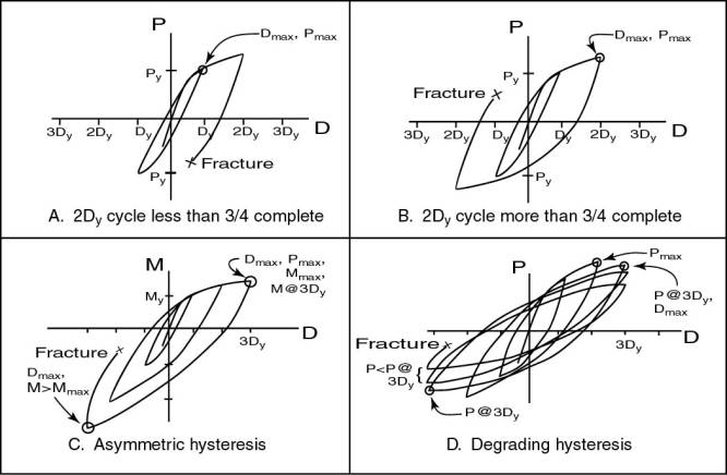
MAX DEFLECTION, Dmax
Most of the database source documents report the history of the deflection measured at or near the actuator. For a typical cyclic test, the maximum deflection recorded in the database is that deflection reached at least once in each direction without brittle fracture. That is, at least three-quarters of a cycle must be complete, as indicated by examples A and B in Figure 4. Dmax is used to calculate the total story drift.
MAX. FORCE, Pmax OR MAX. MOMENT, Mmax
Most of the database source documents report the relationship of the actuator displacement to either the applied force or a calculated moment. If both are reported, the database records force values only. If only moment is reported, the database records those instead. The maximum force (or moment) is the maximum absolute value of force (or moment) reported at any displacement value less than or equal to Dmax. In other words, Pmax, like Dmax, must come from a cycle that is at least three quarters complete. Figure 4 illustrates how Pmax is taken from different force-displacement histories.
1% DEFLECTION
Story drift is a convenient measure of structural deformation. It includes both elastic and inelastic contributions from all structural components: beams, columns, panel zones, and connections. Its use facilitates comparison of multiple tests because it does not depend on estimates of yield deflection. Because design requirements are frequently in terms of drift, it is also more useful than inelastic measures of deformation, such as plastic hinge rotation.
In subassembly tests, equivalent story drift can be measured assuming that beam and column supports represent inflection points. With beam tip control, equivalent story drift is calculated as the ratio of the measured deflection to the beam tip-column centerline length. With column tip control, it is the ratio of measured deflection to column height.
The 1% deflection, then, is just one percent of the relevant length. It is approximately equal to the deflection corresponding to a 0.01 radian rotation between the beam and column chords. It is a useful value for reporting results, because larger limiting deflections can be expressed as multiples of this value. Coincidentally, pre-Northridge beam-column assemblies of conventional design tend to reach their elastic limit at a story drift of about 1%.
HYSTERESIS
Strength degradation has been made an important issue in various acceptance criteria. Therefore, an effort has been made to characterize the specimen hysteresis with a few values. While a rough “backbone” curve can be constructed from these values, a more complete description of hysteresis is generally available (and should be sought) in the reference documents.
The database records drifts and force (or moment) levels at the following points:
1%, 2%, 3%, and 4% equivalent story drifts
Maximum deflection, Dmax
Maximum force (or moment), Pmax
Figure 4 illustrates how maximum values are taken from various types of hysteresis curves given in reference documents. If the specimen failed before reaching specified drift levels, the force values beyond that point are recorded as “na.”
TOTAL STORY DRIFT
As noted above, total story drift is calculated as the ratio of Dmax (defined above) to the relevant length (column height or beam cantilever length) and expressed as a percentage. For the range of interest here, total story drift is approximately equivalent to the relative chord rotation between beam and column centerlines, expressed in radians.
As defined above, Dmax represents the largest deformation level for which one full load cycle is essentially complete. Some guideline documents may define capacity differently, for example, the deformation at which two cycles are completed.
FIGURE 1: CONNECTION TYPES
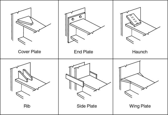
FIGURE 2: WEB CONNECTION TYPES
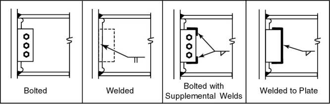
FIGURE 3: TEST CONFIGURATIONS AND LOADING PROTOCOLS
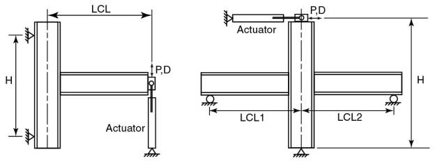
1-side configuration with bm tip control 2-side configuration with col tip control
FIGURE 4: DEFINITION OF DATABASE FORCE AND DISPLACEMENT VALUES